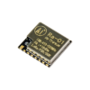
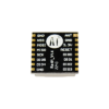
Ai-Thinker New Products Lora Spread Spectrum Wireless Module 433M SX1268 Chip Upgrade SX1278
99 in stock
LoRa™ modem
• Support FSK, GFSK, MSK, GMSK, LoRa™ and OOK modulation methods
• Support frequency band 410MHz~525MHz
• Working voltage is 3.3V, maximum output +20dBm, maximum working current is 105mA
• Low power in receiving state Power consumption characteristics, the receiving current is 12.15mA, the standby current is 1.6mA
• High sensitivity: as low as -140dBm
• Small size dual-row stamp hole patch package
• The module adopts SPI interface, uses half-duplex communication, with CRC, up to 256 words Packet engine
₹342.00 ₹700.00 Excluding GST
99 in stock
CompareLoRa Module Ra-01
LoRa Modules are long range low power RF Modules.
Great for IoT applications to send sensor data to the cloud over long ranges.
Developed by our team Ai-Thinker, the manufacturer of the ESP8266 and ESP32 wifi modules, this Ra-01 LoRa (Long-range Radio) module will take your IoT projects the distance with communication over a long-range spread spectrum. This form of wireless communication results in a larger bandwidth, increasing interference resistance, minimizing current consumption, and increasing security.
This module uses SX1278 IC from SEMTECH and works on a 433MHz frequency. Frequency hopping—which gives you that sweet balance of quality signal transmission will cover a range of 420-450 MHz.
With the LoRa Ra-01, you don’t have to compromise in the balance of range, interference immunity, or energy consumption. The technology behind this IC means that it’s perfect for those projects requiring range and strengt
Applications Of RA01 LoRa Module
· Remote control and data collection system
· AMR(water meter, ammeter and gas meter) automated meter reading
· Wireless handheld unit, oil field, mining area, construction site, factory
· Industrial data collection, transmission and intelligent control
· Wireless alarm system
· Smart home system
· Baby monitor, Hospital calling system
· Small size wireless data terminal


|
Model |
Ra-01 |
|
Package |
SMD-16 |
|
Size |
17*16*3.2(±0.2)mm |
|
Communication Interface |
SPI |
|
Programmable bit rate |
Up to 300Kbps |
|
Frequency Band |
410~525Mhz |
|
Antenna Type |
Spring antenna, gain 2.5dBi |
|
Maximum Transmitted Power |
18±1dBm |
|
Average operating current |
433Mhz: TX 93mA; RX 12.15mA; Standby 1.6mA 470Mhz: TX 97mA; RX 12.15mA; Standby 1.5mA |
|
Supply Voltage |
2.5V~3.7V, typical value 3.3V |
|
Operating Temperature |
-35℃~+85℃ |
|
Storage Temperature |
-40℃~+90℃, <90%RH |
Recommended working environment
| working environment | name | Minimum | Typical value | Max | unit |
| Supply voltage | VDD | 2.7 | 3.3 | 3.6 | V |
| Operating temperature | TOPR | -20 | 25 | 70 | °C |
| IO level | VIO | 2.7 | 3.3 | 3.6 | V |
| Digital input low level | VIL | – | – | 0.2 | V |
| Digital input high level | VIH | 0.8 | – | – | V |
| Digital output low level | VoL | – | – | 0.1 | V |
| Digital output high level | VoH | 0.9 | – | – | V |
Application
-
Automatic meter reading
-
Smart home and security system
-
Industrial monitoring and control
-
Home and building automation
-
Remote irrigation system
-
Wireless sensor data collection
2 Interface definition
2.1 Ra-01/Ra-02 module pin diagram
2.2 Ra-01/Ra-02 module pin function definition
| Pin number | Pin name | Function Description | |
| Ra-01 | Ra-02 | ||
| 1 | – | ANT | antenna |
| 2 | 1, 2 | GND | Grounded |
| 3 | 3 | 3.3V | 3.3V power supply |
| 4 | 4 | RESET | Reset |
| 5 | 5 | DIO0 | Digital IO0, software configuration |
| 6 | 6 | DIO1 | Digital IO1 software configuration |
| 7 | 7 | DIO2 | Digital IO2 software configuration |
| 8 | 8 | DIO3 | Digital IO3 software configuration |
| 9 | 9 | GND | Grounded |
| 10 | 10 | DIO4 | Digital IO 4 piece configuration |
| 11 | 11 | DIO5 | Digital IO5 software configuration |
| 12 | 12 | SCK | SPI clock input |
| 13 | 13 | MISO | SPI data output |
| 14 | 14 | MOSI | SPI data input |
| 15 | 15 | NSS | SPI chip select input |
| 16 | 16 | GND | Grounded |
Ra-01 module package size drawing
Dimensional drawing of Ra-01
Ra-01/Ra-02 module size comparison table
| Module model | Length(mm) | Width (mm) | Height (mm) | PAD size (mm) | Pin pitch (mm) | Shielding shell height (mm) | Board thickness (mm) |
| Ra-01 | 17 | 16 | 3.2 ±0.1 | 1x 1(bottom layer), 1.778 x1.27(bottom layer of antenna pad) | 2 | 2.2±0.1 | 1.0±0.1 |
3.3 Ra-01/Ra-02 module PCB package drawing
Figure 6 Ra-01 module PCB package diagram
Note: When laying out the board, try to put the module on the side of the board with the antenna facing outward. No components should be placed at the bottom of the antenna or near it. The module should be as far away as possible from power components and electromagnetic components, such as thyristors, relays, inductors, buzzers, and horns.
| Weight | 0.002 kg |
|---|
|
Model |
Ra-01 |
|
Package |
SMD-16 |
|
Size |
17*16*3.2(±0.2)mm |
|
Communication Interface |
SPI |
|
Programmable bit rate |
Up to 300Kbps |
|
Frequency Band |
410~525Mhz |
|
Antenna Type |
Spring antenna, gain 2.5dBi |
|
Maximum Transmitted Power |
18±1dBm |
|
Average operating current |
433Mhz: TX 93mA; RX 12.15mA; Standby 1.6mA 470Mhz: TX 97mA; RX 12.15mA; Standby 1.5mA |
|
Supply Voltage |
2.5V~3.7V, typical value 3.3V |
|
Operating Temperature |
-35℃~+85℃ |
|
Storage Temperature |
-40℃~+90℃, <90%RH |
Based on 0 reviews
Be the first to review “Ai-Thinker New Products Lora Spread Spectrum Wireless Module 433M SX1268 Chip Upgrade SX1278”
You must be logged in to post a review.
You may also like…
-
Ewelink Devices, DIY Mode Switches
Sonoff Basic R2 WIFI Smart Switch With Timer Internet Work With AMAZON Alexa,google Home ,Nest
 Ewelink Devices, DIY Mode Switches
Sonoff Basic R2 WIFI Smart Switch With Timer Internet Work With AMAZON Alexa,google Home ,Nest
- ETL Certified
- Remote ON/OFF–Turn electrical devices on/off from anywhere
- App Support –Free iOS and Android mobile App eWeLink
- Sync Status–Real-time device status provided to App
- Timing–Set scheduled/countdown/loop timers to turn on/off at specified time
- Share Control– Control your smart home together with your family
- Scene–Turn on/off a gang of devices with one tap
- Smart Scene–Triggered on/off by temp, hum or other environmental conditions from sensor
- Compatibility –Works perfectly with Amazon Alexa, Google Assistant, IFTTT
SKU: M0802010001 -
Ewelink Devices, DIY Mode Switches
SONOFF BASICR3 – WIFI DIY Smart Switch With Timer Internet Work With AMAZON Alexa,google Home ,Nest
 Ewelink Devices, DIY Mode Switches
SONOFF BASICR3 – WIFI DIY Smart Switch With Timer Internet Work With AMAZON Alexa,google Home ,Nest
- Remote ON/OFF–Turn electrical devices on/off from anywhere
- App Support –Free iOS and Android mobile App eWeLink
- Sync Status–Real-time device status provided to App
- Timing–Set scheduled/countdown/loop timers to turn on/off at the specified time
- Share Control– Control your smart home together with your family
- Scene–Turn on/off a gang of devices with one tap
- Smart Scene–Triggered on/off by temperature, humidity or other environmental conditions
- Voice Control –Works perfectly with Amazon Alexa, Google Assistant
- Compatibility –Works perfectly with Amazon Alexa, Google Assistant, IFTTT, Google Nest
- Make one device trigger on/off another one or groups of devices.
- Control SONOFF devices with the utilization of IFTTT supported app and services.
- The DIY Mode allows you to use the REST API to connect SONOFF BASICR3 with your existing home automation system.
- Turn on/off the device when no Wi-Fi access in LAN Mode.
- Share devices with your family to control together.
- Show the real-time status on the eWeLink app for devices.
- Can act a camera to monitor and control devices.
SKU: IM190314001 -
Accessories, Ewelink Devices, Security, WI-FI Smart Home Security
SONOFF DW2-Wi-Fi Wireless Door/Window Sensor Anti Theft Mobile Notification work with Alexa, Google home
 Accessories, Ewelink Devices, Security, WI-FI Smart Home Security
SONOFF DW2-Wi-Fi Wireless Door/Window Sensor Anti Theft Mobile Notification work with Alexa, Google home
-
- Keep linkage with SONOFF smart devices to create various smart scene
- Turn on/off your light with an action
- Notify you when the door/window is opened
- Check the opening and closing status of door/window on APP
- Battery-level display and low-battery reminder
- Allow sharing the sensor with your family to monitor and control of your home
- No gateway required
- Bluetooth low energy pairing
- Support to check history record on APP
- Low-power Wi-Fi transmission for more lasting work time
- Peel and stick installation, quick to use
Note: SONOFF DW2 doesn’t come with batteries into the package.
SKU: M0802070002 -


There are no reviews yet.